|
|
|
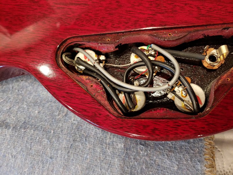
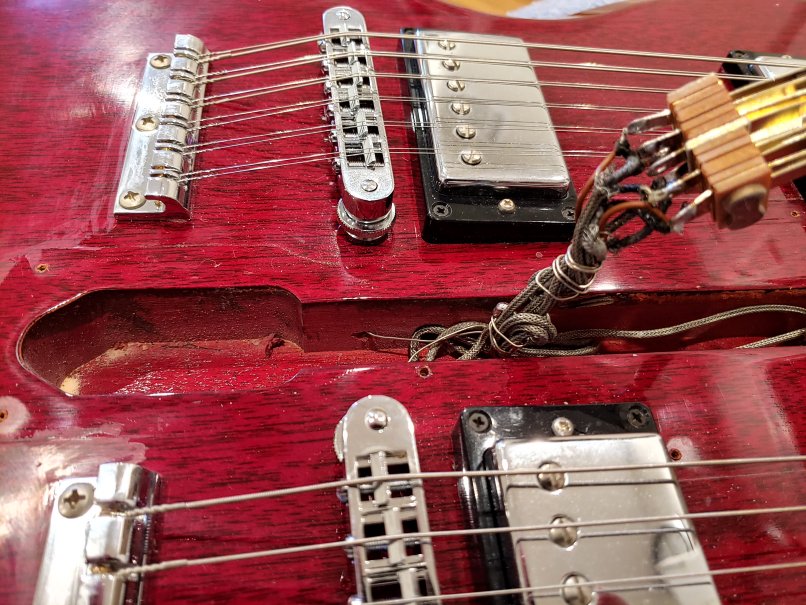
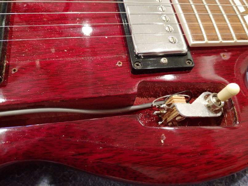
And then there's the wiring. Here are pictures showing how it was originally was done, taken durring disassemby. The neck select switch has been pulled out from the body to show the wiring better. There are 2 switches. The switch between the 2 bridges (above right)selects the neck: one or the other neck, or both. The pickup on the lower pickguard (left) selects the pickups - for both necks. There is one volume and one tone control for each neck (above left). So, you can't just switch between the 12-string neck on the rythm pickup to the 6-string neck on the treble pickup. You have to switch the pickups AND the neck.
Also, like every Gibson guitar I've ever played, there's the anoying hum. Most of the wiring is via shielded cable, with the shield soldered to the potentiometer cases (see the picture above left). Notice in the picture above right, the the thin wire coming out of the hole beneath th bridge? That is a ground wire from the bridge to the cable shield (all 4 pickup cables are wrapped together at this point also). They haven't changed their wiring methods in over 50 years.
The problem is that there are vulnerable places for picking up ourside signals (hum) - the switches and the tone control wiring.
And that ground connection to the bridge - you can reduce this hum drastically while playing by using your body as an extra ground as long as you keep one hand on the strings. Everybody seems to think this is a good idea. Also a fun way to get a good electrical shock if you're using an old 1950's amp with a 2 prong electrical plug (please don't do this).
|
|
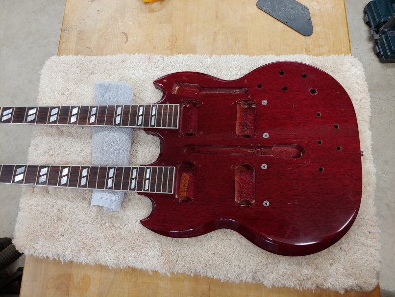
Here it is all disassembled. Despite all of my sniveling about the wiring, this guitar is beautifully built. Still heavy, and I weighed some spare Kluson tuners I had - they're 1.12 Oz (31.76 g) each. That makes about 1 lb 4 oz (.572 kg) of weight out at the end of the neck! No wonder it's unbalanced. Moving the 12 string tuners closer together (like the Epiphione version) would help a little, but the wider spacing does make it easier when you're changing strings.
I decided at this point to thoroughly clean and polish the body. I used “Super Nikco” - a french product for cleaning and polishing violins. The instructions are in french, but you can download them from the interweb in your language. Does a wondeful job! I also cleaned the fingerboard with lemon oil from StewMac.
|
|
|
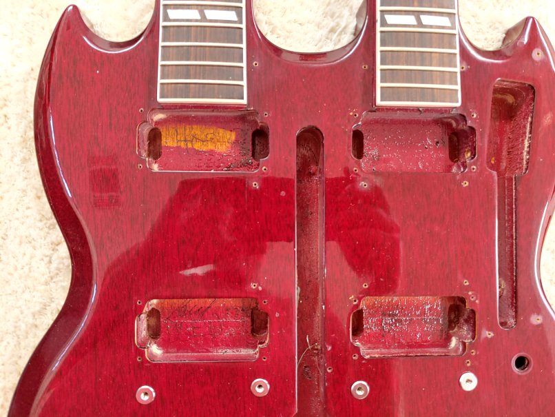
Closeup of the body. The builders at Gibson left some writing - their names or initials in the pickup cavities. I can't read them - can you?
|
|
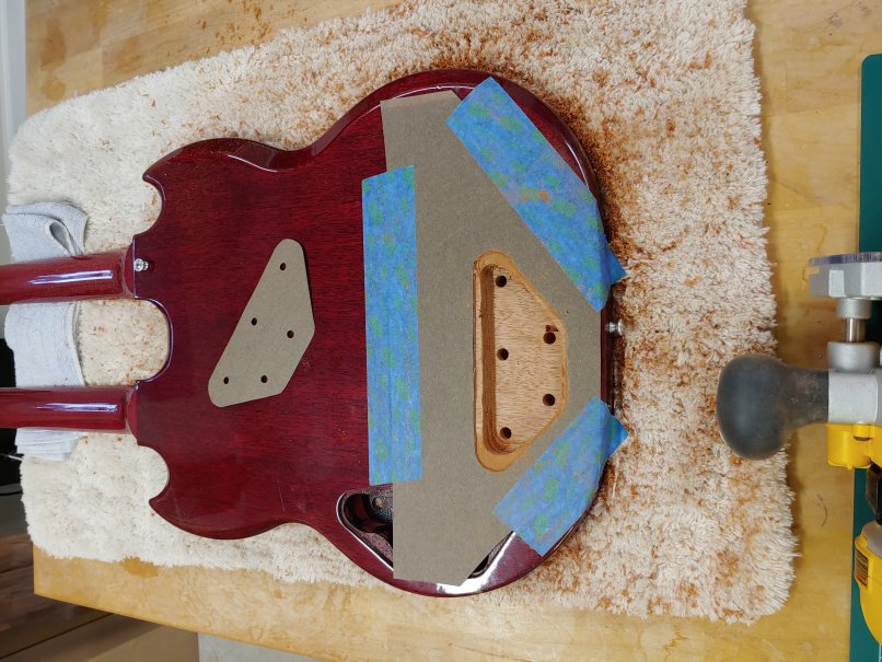
Here it is after routing out the body for the controls for the 12 string side. I made 2 templates: One for routing and one for drilling holes and wiring. I made the latter one first, by tracing the original back cover plate and marking the placement of the original holes for the 4 pots and jack, I made the routing template by just tracing the cover plate. The actual shape of the cavity is a mirror of the original. That way, the placement of the original output jack and the new output jack are next to each other.
I drilled the holes from the front of the guitar first using the template. Then I flipped it over and placed the routing template around the new holes. Taped the template to the body, picked up the router, took a deep breath and went at it. I was sweating bullets but it went smoothly.
I routed the new cavity to the same depth as the original, which leaves about 1/8" of wood between the bottom of the cavity and the front of the guitar.
|
|

|
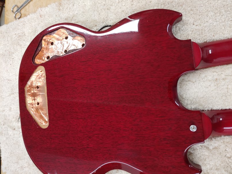
Closeup of the body after lining the cavities with copper foil from StewMac.
This stuff is the greates thing since 2-ply toilet paper! On my first rebuild of the explorer, I used thin sheet brass cut and bent to line the cavity. Cut my hands to ribbons! This stuff is like using masking tape, and the adhesive seems to be conductive, so all of the pieces are connected electrically when you overlap them. Cuts easily with scissors.
|
|
Another view. You can just barely see the hole I drilled between the 2 cavities. Only 2 wires go through here. More on that later.
|
|
|
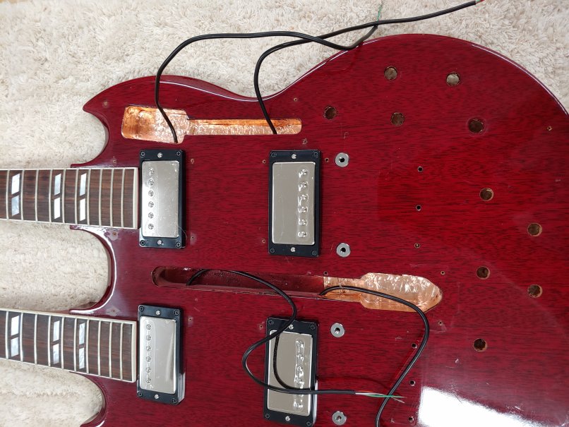
Pickups inststalled and foil applied to the cavities for the switches. The pickups still have their protective plastic on.
The pickups are SH-1 Bridge and neck, 2 of each, from StewMac. I was going to use Gibson 490's like I did with the explorer, but I opted for these because they're a little "hotter". I really like them now that I've tried them. They're split-coil, like the 490's.
|
|
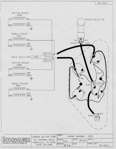
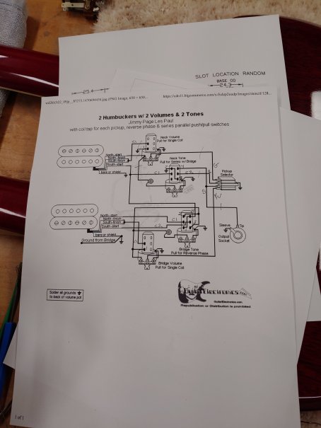
Here is the original Gibson schematic, and the Jimmy Page schematic I used, downloaded from GuitarElectronics.com. It's available from a lot of different places, but this one is the easiest to read and follow. Notice the pecil marks - I put a slash mark on each wire in the schematic as I wire and solder things up. Helps keep track of what's been done and what hasn't. The letters are for the color of the wire used.
|
|
|
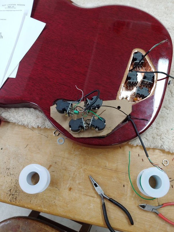
Wiring it all up. Had to do this twice. I used CTS push-pull pots, DPDT 500K (CTS #340S 3910) from StewMac. They were the only ones that were short enough to fit (the body is not very thick). And they just barely fit - I almost couldn't put the black plastic cover plates back on.
I originally got 8 push-push pots from MojoTone.
Think about it - with push-pull pots, you have to reach down, grab the pot, and pull it out half of the time. With push-push, you just smack the pot and go back to playing, Much faster.
Problem was, they were too tall for this guitar by about 2 mm. I could have routed both cavities a bit deeper, but that would have left very little wood between the bottom of the cavity and the top.
I will probably use 4 of them to replace the push-pull pots in the explorer some day when I'm bored and want something to do. Maybe use the other 4 in the Les Paul?
Anyway, as you can see in the picture at left, there is very little room to wire up things within the cavity -like building a ship in a bottle. So I made a copy of the drilling template on corrugated cardboard, and used that to hold the pots while I wired everything up. Much easier.
No, I did not solder ground wires to the pot cases. With the copper foil, it would serve no purpose.
|
|
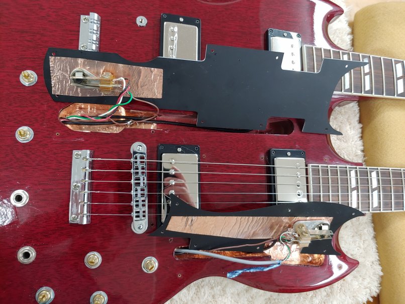
Noise shielding really is an art. I have used just 2 basic principles here: the "Faraday Cage" and star grounding. The Faraday cage here consists of all of the copper foil. The star ground means ALL ground connections are to ONE Single point - in this case (and any guitar) it's the ground lug on the output jack.
There are ground lugs on the 2 pickup select switched in the picture at right. They are on the bodies of the switches and are in electrical contact with the copper foil on the black plates. The brown colored wires connect to the ground lugs and go straight to the output jack ground.
There are 2 output jacks on this thing (a switched mono jack for the 12-string, and a stero jack for both. A mono plug in this jack gets the 6-string output (and the 12-string output would be grounded, except the 12-string signal is switched at the mono jack - if there's a jack plugged into the 12-string jack, the stereo jack doesn't get the 12-string signal. I thought I was real clever to think that up.
|
|
|
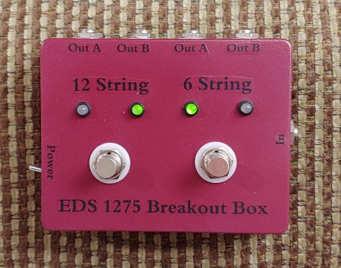
Here is the break-out box ("BOB"). It takes the stereo output (input on the right) and routes the 12-string signal to one of two outputs (left half), and does the same for the 6-string signal (right half). Each footswitch toggles between th associated 2 outputs (and the indicator LEDs). In this picture, the 12-string signal is going to its "Out B" and the 6-string signal is goint to its "Out A". The footswitches can be stomped on at the same time, and in this case it would switch the 12-string to "Out A" and the 6-string to "Out B". If both "Out A" outputs are connected to the same amplifier, and both "Out B" outputs are left unconnected to anything, toggling both foot switches changes which one goes to the amp.
The power switch on the left end is just for the power for the LEDs.
|
|
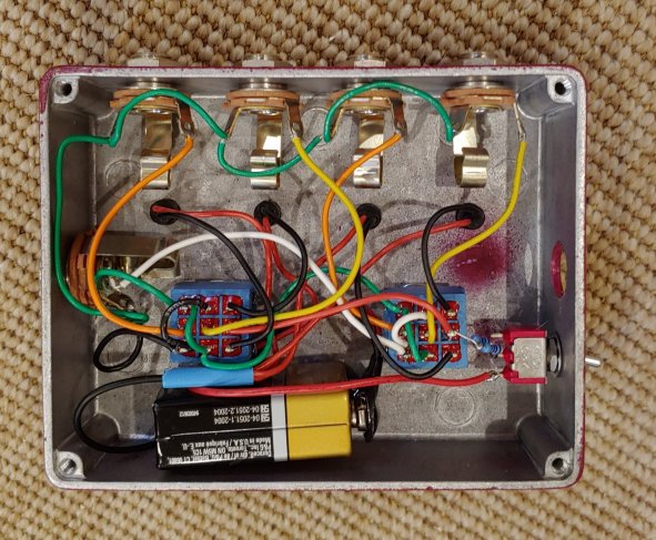
Here is the inside of "BOB". Not all that complicated, really. The red and black wires (and the 2 resistors at the toggle switch) are just for the LEDs. All of the green wires are ground, and the yellow and orange wires are for the "Out A' and "Out B" outputs, respectively. Notice that the unselected outputs get grounded just to keep things quiet!
One issue I've had is that ALL stereo cables that I've found to use (between the guitar and "BOB") have 2 conductors inside one shield. That doesn't work - there's a lot of cross-talk, or leakage between the 2 signals! I still need to find some 2-conductor 2-shield wire (like 2 mono shielded cables wrapped together) and make my own.
|
|
